
Firstly I've looked in the Sticky book but the DC wiring digram there doesn't fit with what I've got.
On the loom at the back end it has -
Red - this needs to go to the battery. I think this should be on the far right on the regulator?
Purple - could go onto the same terminal as the red and feed the DC horn
Greens - both jointed together. One is going to the battery and the other to the headset but where is this connected on the regulator?
Brown - power to the headset but now DC ? and where does it go on the regulator?
Grey - going to the headset via the back brake but where does it go on the regulator?
The regulator has some colour coding on it from left to right Yellow, Blue,Green, Red and Black???
Wiring DC Casa Loom and 5 Pin 'DC' SIL Regulator
I take it the Casa loom is the same as the standard Innocenti SIII battery type? But what DC drawing are you trying to follow? Also, does a SIL DC regulator exist, or do you mean a Ducati (vespa) reg/rec?
Kev.
Kev.
The Casa loom doesn't seem to follow anything in Sticky's book. I've tried to follow the 'SIL Indian Electronic 12V DC (with battery and no indictors)'
I'm unsure what the regulator was designed for but it's the '5 pin' DC I bought from a Lambretta dealer ( I can't remember which dealer)
If I could find out the imputs and outputs for the 5 pin regulator, I could hopefully work things out from there. If anyone could help?
I know the green wires are normally for the ignition but would they also go through the battery for a DC supply?
No, the green ignition wires will not go through the battery, but direct to the CDI.
If I'm looking at the same diagram as you, SIL 12V DC system, I don't think that it is a SIL factory wired scoot, but one with an AF DC conversion (and unless it's a unique reg/rec the drawing is wrong as well). I've never come across one of the ignition switches used on that diagram either but would like to get hold of one as it would come in handy for using 5 pin reg/recs as Ducati intended, in fact there is no need for the battery switch in the drawing as the ignition switch could have provided that function. So, unless you have an AF DC 6 wire stator and it's original rectifier, with a 5 pin vespa reg/rec you are going to be limited to AC main lights, with battery for horn, brake light and parking lights.
I don't recall seeing any machine using the colours on your reg, is there any letters written next to the terminals?
Please see a pic of the regulator, sorry about the size. It goes from left to right Yellow Blue Green Red Black 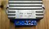
I don't know if I was dreaming but I though I saw a reply to this thread offering some advice as to where the wires probabay go
I don't know if I was dreaming but I though I saw a reply to this thread offering some advice as to where the wires probabay go
-
lammydave
- registered user
- Posts: 200
- Joined: Wed Jan 07, 2009 1:13 pm
- Main scooter: Li150Special RT195
- Location: Ashford, kent
- Contact:
this was a reply i got a couple of years ago .. worked for me....
ok ive just done this so i know how it all works. I bought a ducati ac to dc regulator from cambridge lambretta. I've got a battery wiring loom fitted. On my reg the first two slots have an G on them then there is a B a C and then the earth. I am going on original config here:
& this also depends on the letter config on your regulator
from right to left:
connect earth in end (black)
usually the one next to earth is left blank
then you have the battey terminal marked B, the red from loom & grey go in here
then you brown & purple in the next
and finally your yellow from stator goes into the first socket.
This gives the original config of your horn, brake light & side light running off battery. But you can swap these about. The pro's of having a battery is that you have great lights all the time, but the cons is that you battery fails your shafted.
I bought a little toggle switch from maplins a made a simple mod.
i basicly cut all wires from loom apart from the red and put them into one connector & plugged this onto the output of the toggle switch. Then on one end of the switch i put a feed from the battery & on the other end i put a feed from the stator and then just tightened the switch onto the frame lug. This way if the battery fails then you just flick the switch & then your running straight off the stator or if your stator failed like mine did & i was stranded with no lights..then i flicked it down & my lights were running off battery & gave enough power foir me to get to safety.
Li150 S2 1959. Li150 Special 1964. GP125 1970. Jet 200 Performer 1981. 1967 Sx150. 1959 Li150 S1. 1968 li125 Series 4