Lambretta Points Ignition...

Anything related to Lambrettas... ask tech questions, post helpful info, or just read and learn.
J1MS
registered user
Posts: 1153
Joined: Sat Jan 10, 2009 12:02 am
Contact:

I Took some better pictures as the I Phone is good... but pretty useless at photo's close up
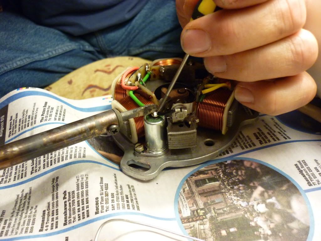
This stator is a Lambretta points ignition system, that needs repairing... There is no spark comming from the stator, or so I have been told....

The points (bad picture I know) are badly soldered as is the condenser. But the problem with the spark is that this stator is battery points....
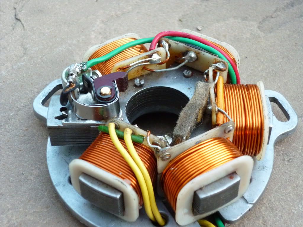
The stator is wired with five double wound lighting coils that supply a common and two lives to feed a Bridge Rectifier, this then feeds a battery which powers the points ignition and lights It looks like its off a Three Wheel Lambro... It will get a looking at then be returned to make sure the owner understands how it needs to be wired as there are a couple of variations on Lambro stators but to all intents and purposes this stator is basically the same as any series three stator...

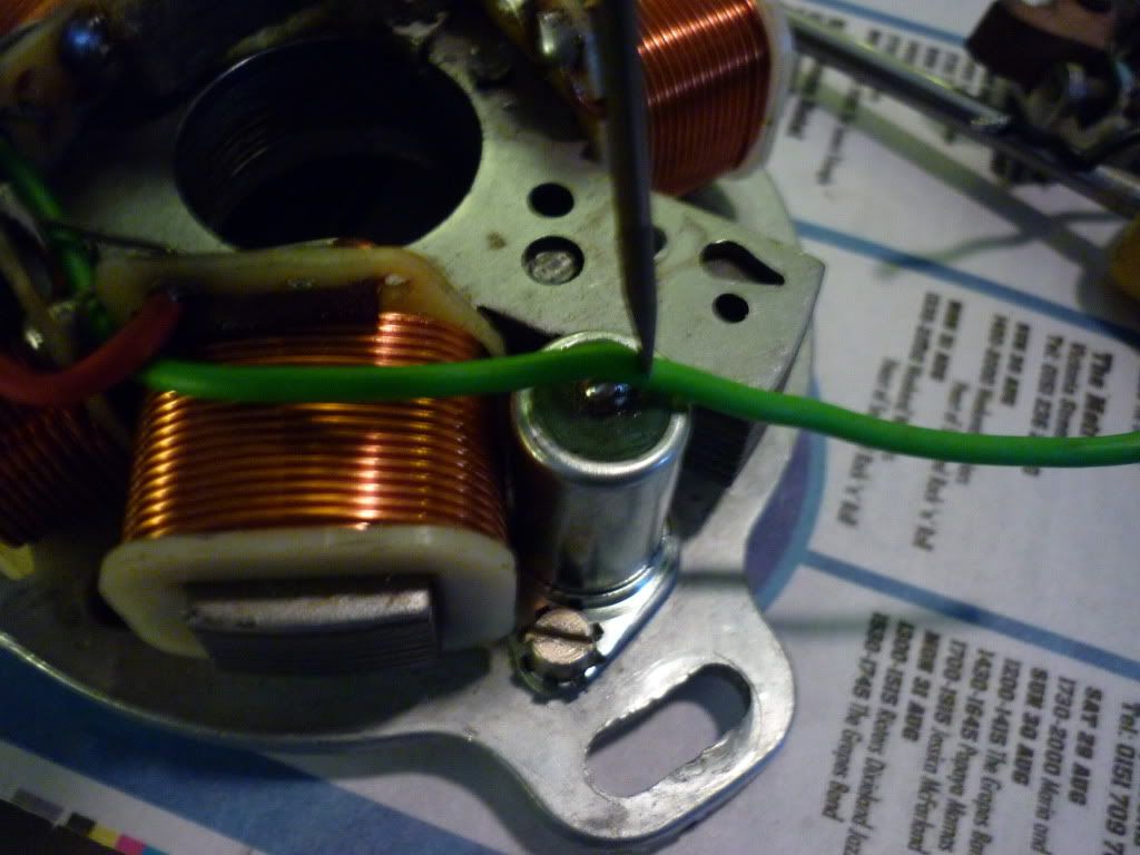
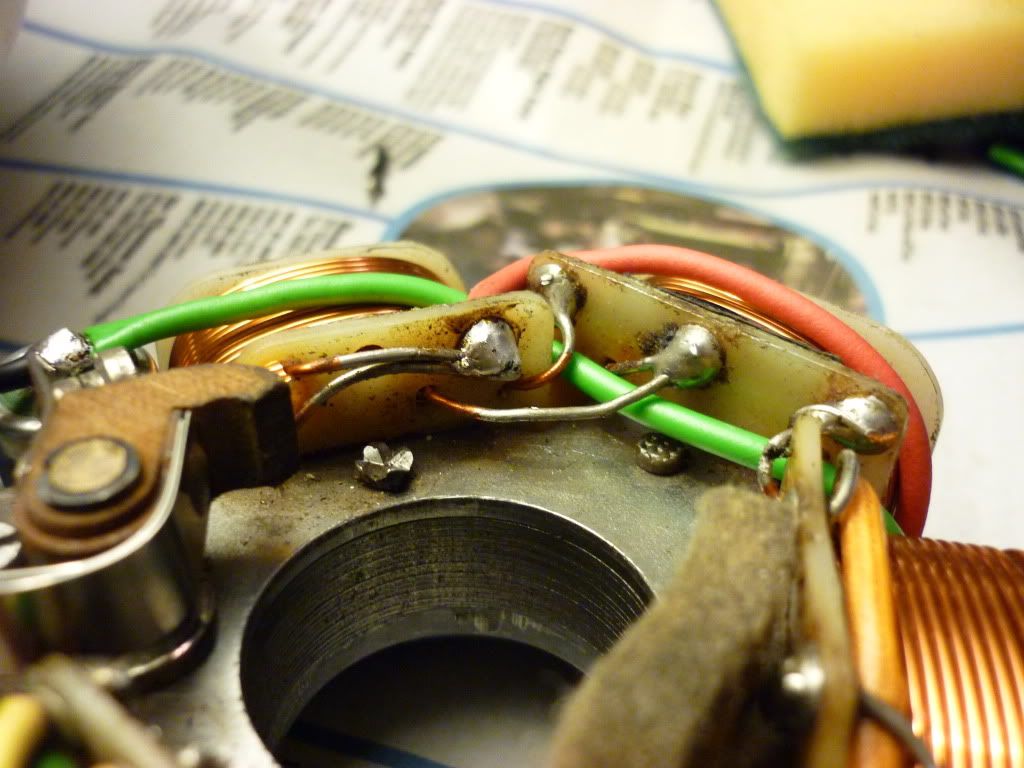
This first picture shows the wiring configuration, not quite standard series 3...
Image

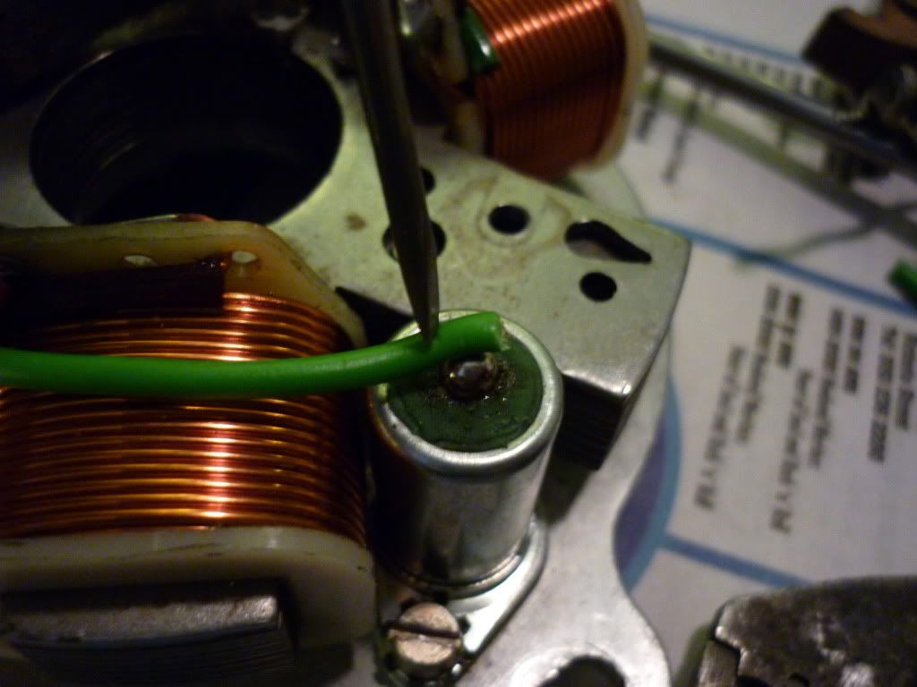
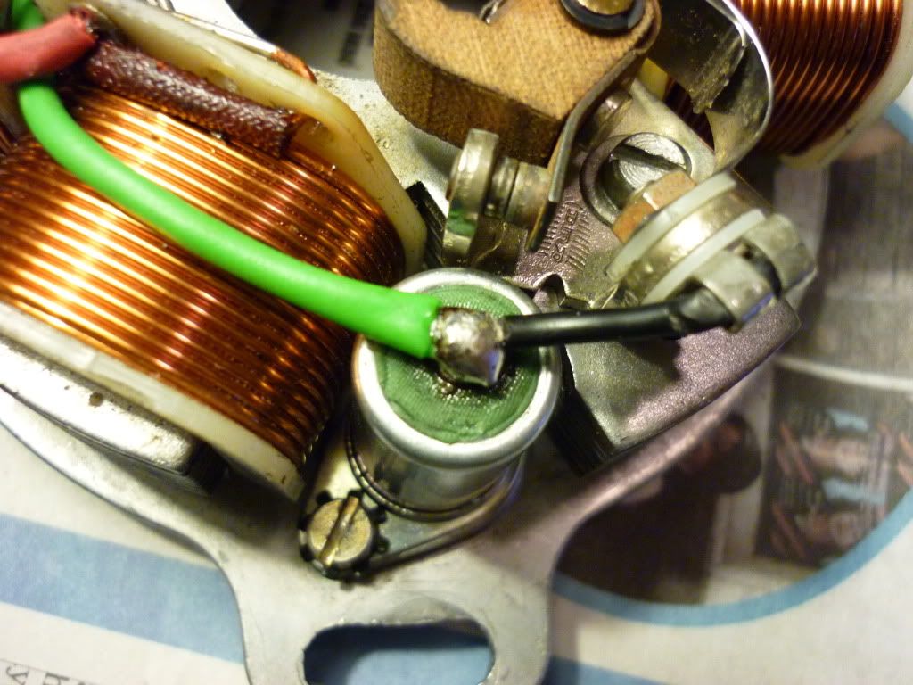
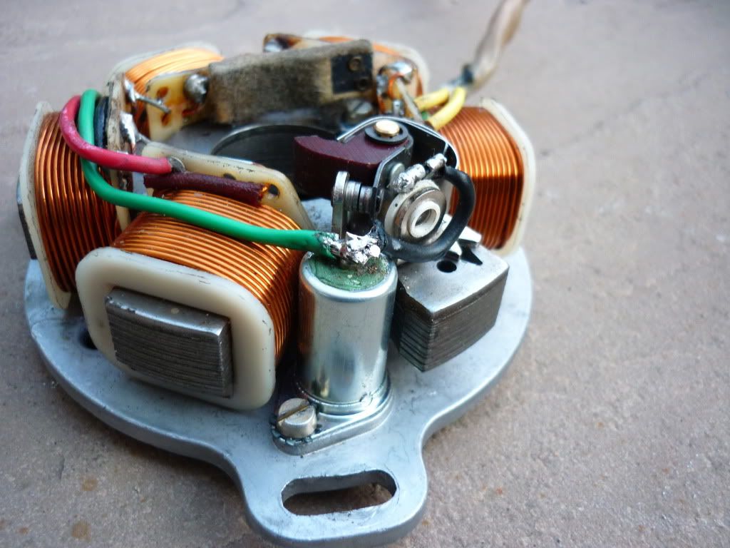
This next photo shows the poor soldering lumps blobbed on, and a dry joint...

Image

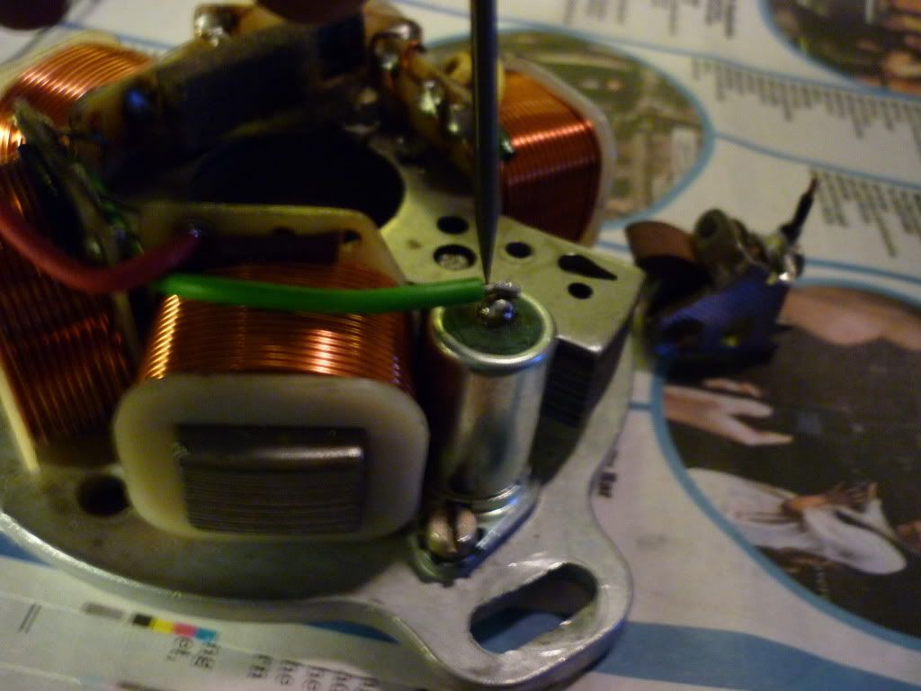
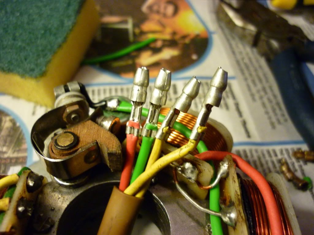
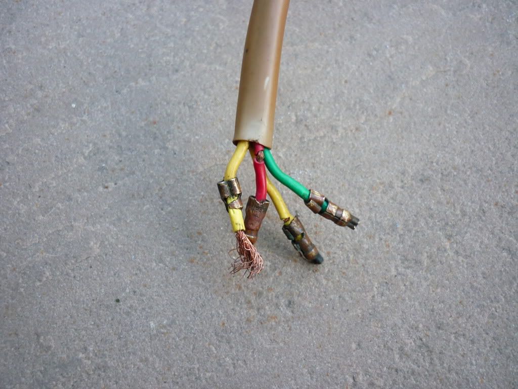
This photo shows the damaged wire Red that needs replacing and a missing terminal... the other terminals are a little corroded

Image

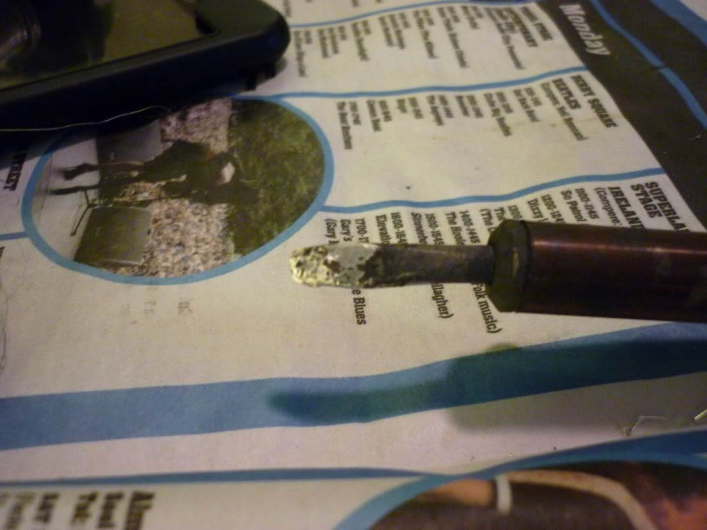
Will post the finished pics when its done... And try and show an easier way (Picture) to get a good soldered joint at the condensor, which is where I quite often see poor results, this might make it easier for anyone trying to fit a new condensor... I hope this will be of help to someone... Now back to the Garage..... Back soon ;)
User avatar
rog60
registered user
Posts: 588
Joined: Fri Feb 13, 2009 7:18 pm
Main scooter: Indian GP200
Location: SWINDON (Wilts)
Contact:

Well, I'm crap at soldering but even I can do a better job than that. :D :D :D :D :D
NO IT'S NOT A F***IN* MOPED!!!!!!
dirtyhandslopez
registered user
Posts: 465
Joined: Sun Mar 22, 2009 5:15 am
Location: Richmond Virginia, USA
Contact:

I'm getting old and the eyes aren't what they used to be, but isn't the wire from the condensor to the points connected on the wrong side of the points?
That's not going anywhere...
User avatar
CANbus
registered user
Posts: 185
Joined: Sun Jan 11, 2009 2:19 am
Contact:

Posts of this nature are invaluable to the longevity of scootering, clear info great photo’s, thanks for posting J1MS
Last edited by CANbus on Fri Aug 28, 2009 10:03 pm, edited 1 time in total.
11111111 = 0xFF
J1MS
registered user
Posts: 1153
Joined: Sat Jan 10, 2009 12:02 am
Contact:

First make sure the tip of the soldering iron is tinned... To do this heat the iron then coat with fluxed solder.. and wipe with a wet spounge to leave a shiny tip... Mines a little old now so its a little worn new tip soon but still shiny which equals a HOT iron..

Image

A new green wire (32/2 tinned copper wire) pulled through the old sleeving mark where it needs cutting I use a sharp screwdriver to mark then cut...

Image

Then mark the other side of the soldered joint again with a sharp screwdriver as only the wire that is to be soldered needs to be reveajed to make a tidy joint...

Image

then trim the wire pre coat the end with a little solder after this is done then put ti in place over the condenser and hold it in place with the small screwdriver at the end of the insulation then solder two photos below
The first one shows the green wire being held in place prior to soldering... The tip of the iron is touched against the wire till the solder is felt softening below, then remove the iron but keep the pressure on the screwdriver for a second or two longer...

Image

Trim the points wire the same way as the green wire was done by marking with a sharp screwdriver then trim lightly coat the tip of the wire with a little solder then again hold in place to be soldered with the tip of the screwdriver... as in photo below and solder as i do use the side edge if its tinned it will heat in a second or two...

Image

The end result is a fairly neat joint... but some condensers are easier than others to solder to, These type a pretty awful...

Image

The replaced red wire and soldered joint...

Image

The connectors now replaced with tinned copper connections..... These fair alot better than plain copper connectors as they are more corrosion resistant....

Image

I hope "How To" this is some help to anyone trying to repair their stator and gives maybe an easier way to get a fairly good result and helps with any soldering that you might undertake....
Now to give it back to its owner...
J1MS
registered user
Posts: 1153
Joined: Sat Jan 10, 2009 12:02 am
Contact:

The connectors used to be available from Maplin and Electromail but there still available from other companies and the crimpers are easy to use and give a factory finish cost for a cheap pair of non insulated crimpers is about £10.00 but a decent pair are from about £30.00 upwards.... just incase if anyone was after a pair ..!!
J1MS
registered user
Posts: 1153
Joined: Sat Jan 10, 2009 12:02 am
Contact:

dirtyhandslopez wrote:I'm getting old and the eyes aren't what they used to be, but isn't the wire from the condensor to the points connected on the wrong side of the points?
To be honest, if they were original points thats the side the wire was supposed to come off... its usually easier to adjust the points the wire acts like a spring and pushes the points against the cam... Originally they would have been wired that way its the new points that are wrong..!!
User avatar
rog60
registered user
Posts: 588
Joined: Fri Feb 13, 2009 7:18 pm
Main scooter: Indian GP200
Location: SWINDON (Wilts)
Contact:

Clear, concise and good photos. Thanks J1MS.
NO IT'S NOT A F***IN* MOPED!!!!!!
dirtyhandslopez
registered user
Posts: 465
Joined: Sun Mar 22, 2009 5:15 am
Location: Richmond Virginia, USA
Contact:

J1MS wrote:
dirtyhandslopez wrote:I'm getting old and the eyes aren't what they used to be, but isn't the wire from the condensor to the points connected on the wrong side of the points?
To be honest, if they were original points thats the side the wire was supposed to come off... its usually easier to adjust the points the wire acts like a spring and pushes the points against the cam... Originally they would have been wired that way its the new points that are wrong..!!
Lovely stuff.
What I was alluding to was the fact that the wire was on the wrong side of the insulator of the points. The following pictures from when you have done the work, the wire goes to the correct side. Or the points in the first group of picture are a type I've never seen. But I am in 'Merica, there's a lot we don't get to see over here...
That's not going anywhere...
User avatar
corrado
Dealer
Posts: 2588
Joined: Thu Jan 08, 2009 1:12 am
Main scooter: Lambretta GP
Location: Top of Blackpool Tower
Contact:

Nice work. A "How to" section would be a good addition to the forum I reckon.
Post Reply Previous topicNext topic
  • Information
  • Who is online

    Users browsing this forum: No registered users and 6 guests