
As this system is running on a standard type stator, weather its Italian, Indian or BGM, Electronic or points condensor....It is essentialy the old 60's style 12 volt dc Conversion....
This conversion is for use only with a modified stator only not a six volt or standard ac Indian or BGM but if modified they can all be made to work (of which a "How to" is on another post) and a Zenor diode will be needed..... AF sells these Zenors for £20 to my knowledge....
But If what your after is a more standard look this is a very good concealed conversion.....This conversion when wired this way allows the use of the fuse to protect the battery circuit and all the original colour coding can be used that means if you put the original wires back where they would have been colour coded evrything works....But if wiring an Electronic try not to use the green terminals on the rectifier junction box and wire direct to the CDI as per original Electronic...
Below... the standard rectifier and the (metal cased mini bridge Maplins about £3.00) rectifier to be fitted ( but the original old style Lucas rectifier can be fitted)...
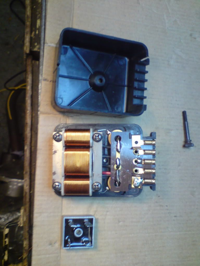
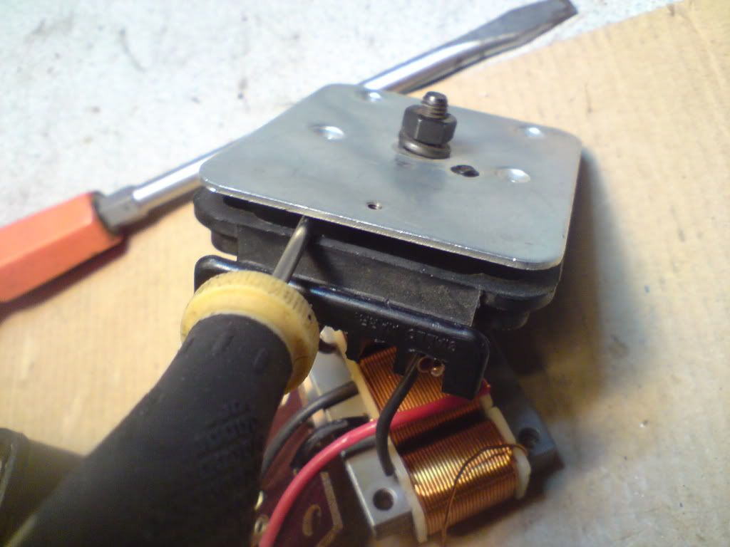
First remove the four screws that secure the coils and de-solder the two diodes and bend the attatched wire straight..

Then pull forward the coils free from the back plate
Now with a flat bladed screwdriver gently lever out the two diodes which will release two of the six connections that need to be detached...
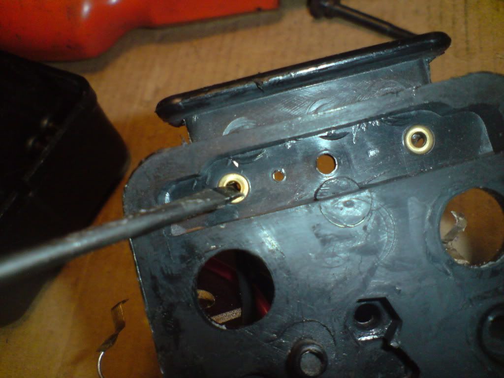
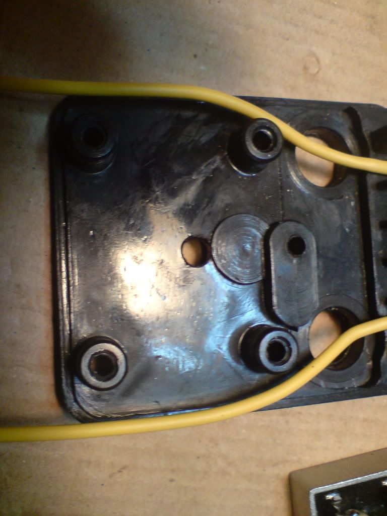
Next undo the small retaining screw that holds the metal backing to the plastic backplate...
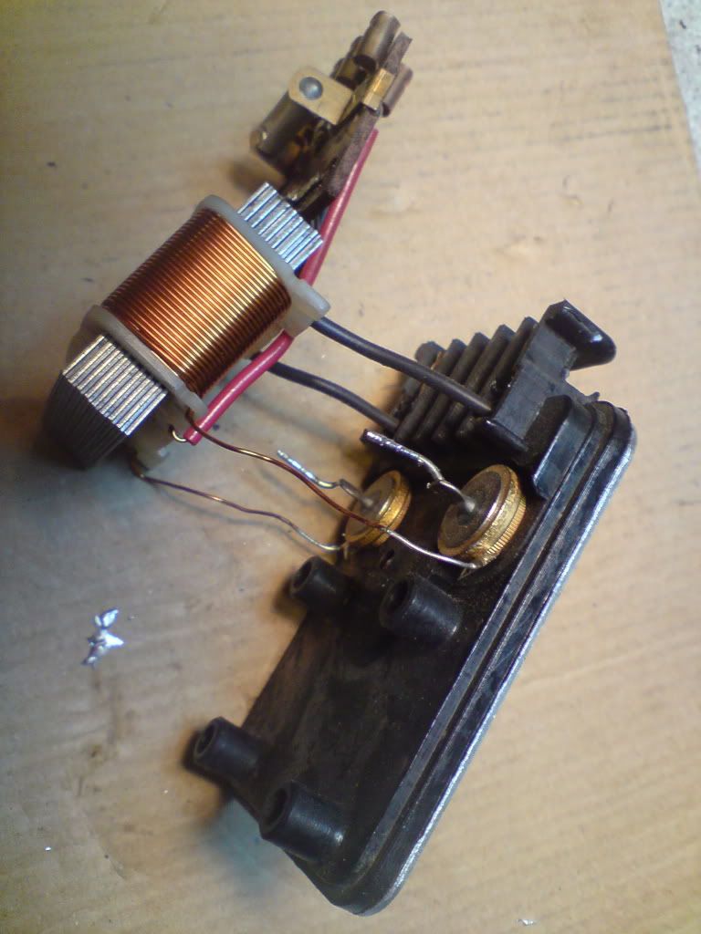
With the metal back removed its possible to see the two connections from both sides....these two connections need to be desoldered with as little heat as possible being transfered to the plastic...
A hot iron carefully placed here will undo these connections in about half a second without melting the plastic...
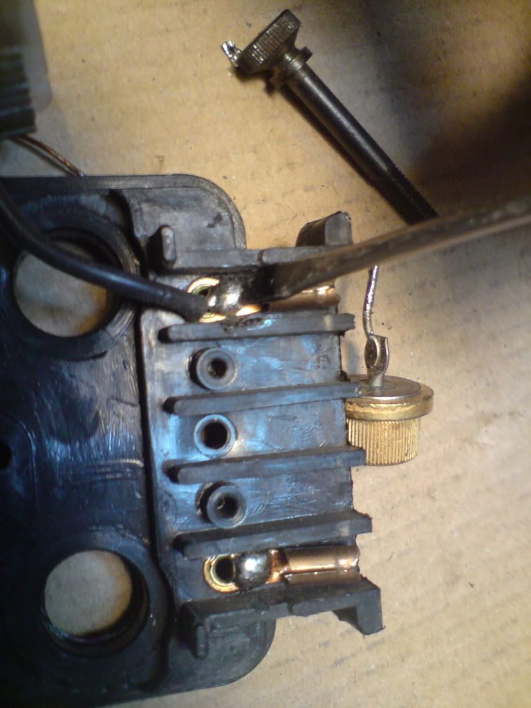
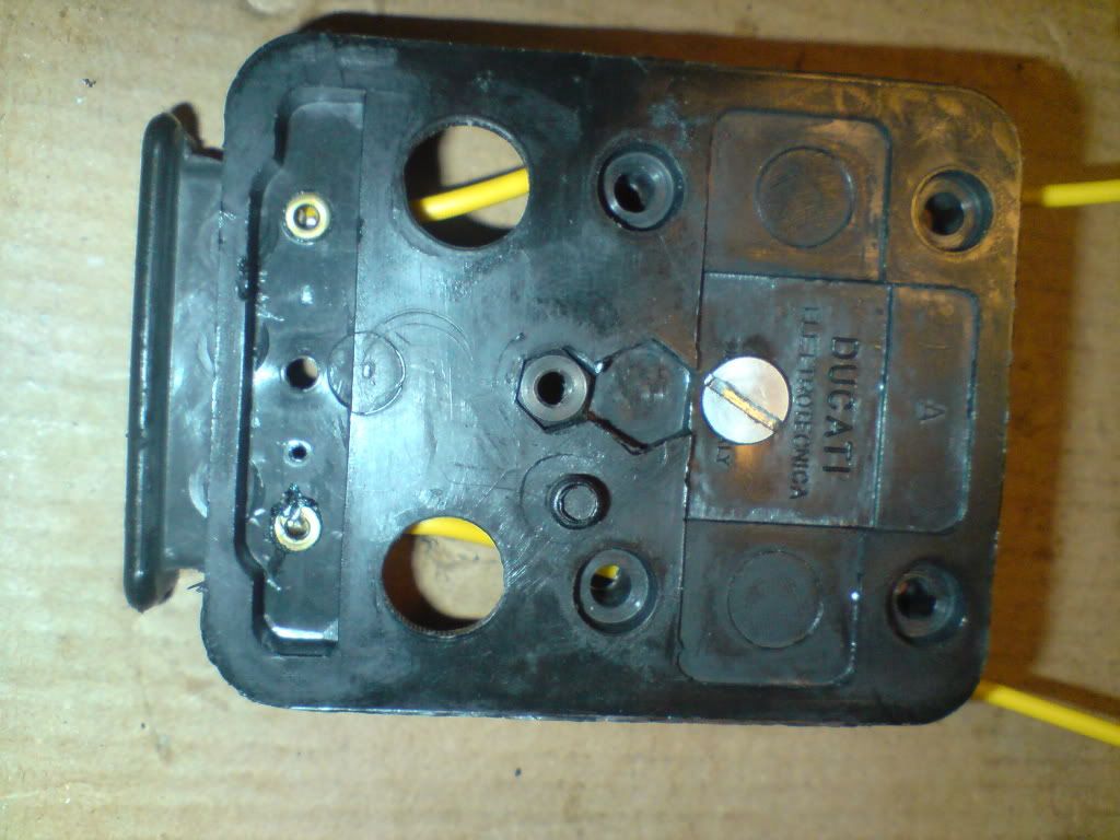
With all the connections removed from the old coils which went to the rectifier connector block....you will be left with this...
As can be seen I have started making the new connections that will supply the dc current and the two ac feeds that will connect to the rectifier...
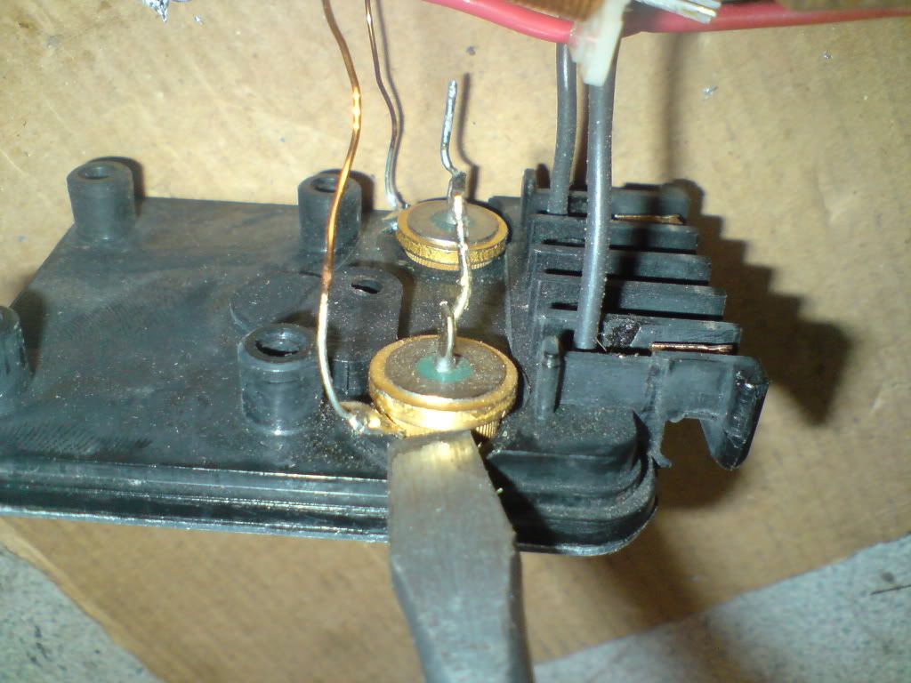
Next you need to drill a hole to secure the new rectifier 5.5mm is Ideal for a 5mm nut and bolt...
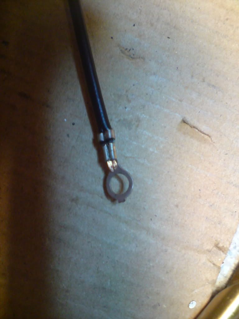
now make a good earth wire fitted with a tag to bolt down....this will earth through the metal back to earth....an insulated cromp terminal can be used
Now fit the regulator with a counter sink 5mm bolt...This will stop the metal back interfering with the bolt...Viewed from the back
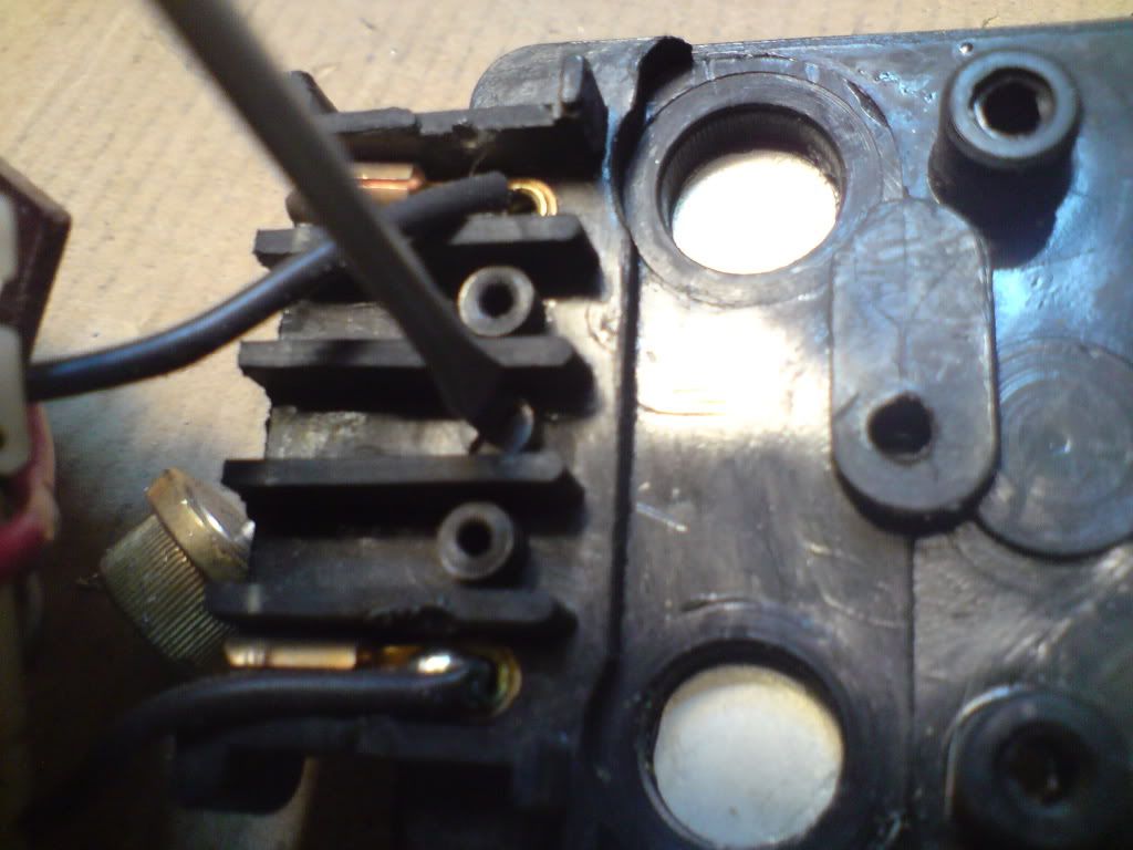
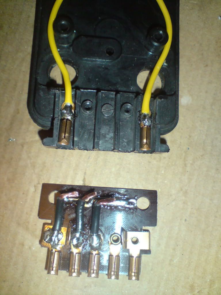
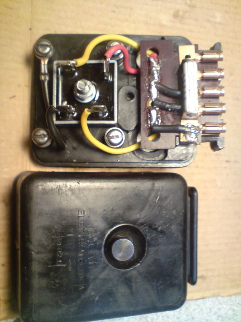
With the rectifier in place and the next phase of wiring completed Which is easily followed using this picture....The two yellow wires that can be seen... These were the two fitted in the earlier picture....The earth wire made earlier can be see now bolted in place....the original bolts need to be cut as they will be to long... or replace them as I have with new shorter ones fitted with a flat and spring washer
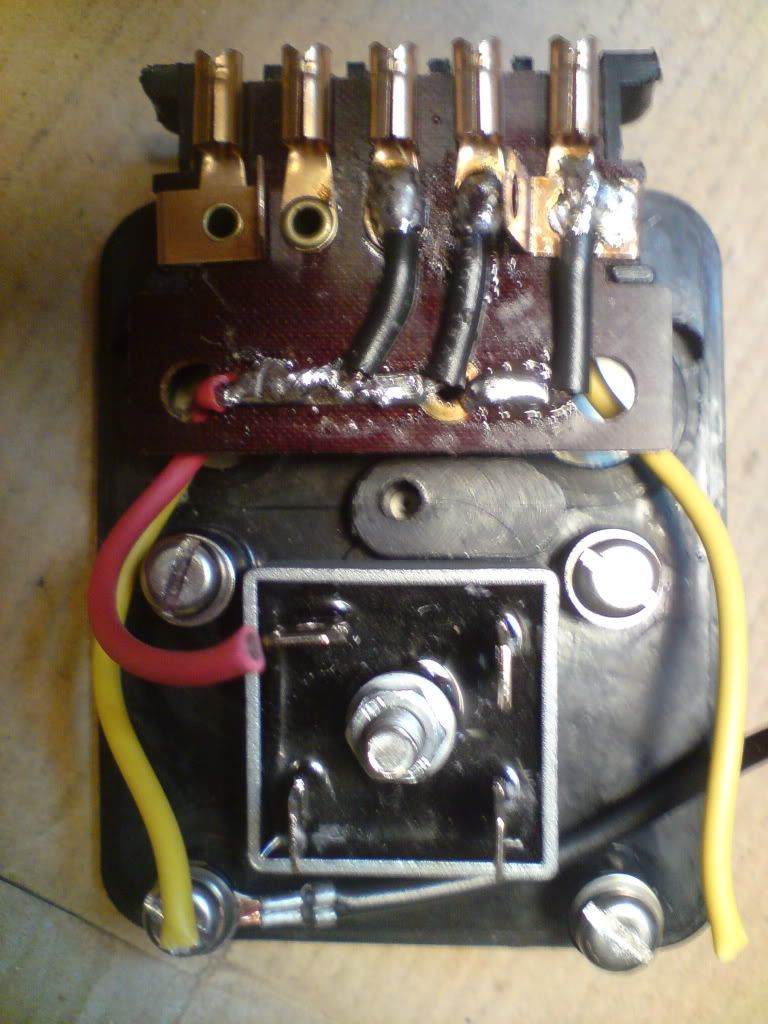
Now the final connections need to be made....the rectifier has 4 terminals the live feed out is the red terminal soldered to the dc output from the rectifier, this is the contact that faces in the opposite direction to the other 3....if you look at the picture you wiil see....the two ac contacts connect the yellows to then last the dc negative this is the earth for the system ....NOTE... this system is wired for use only with a negative earth zenor...
replace the amall screw removed earlier...
now the assembled unit as it looks with the cover back on...

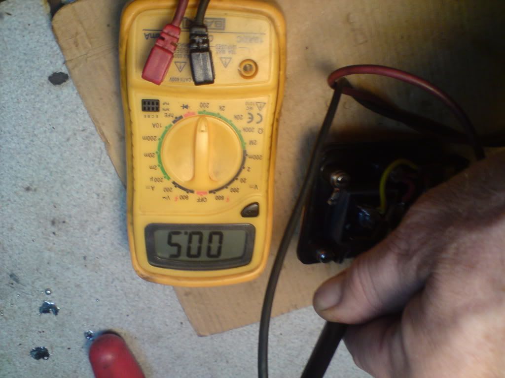
The connections were all checked for continuity between rectifier intput and yellows...then between rectifier output and bullet recepticles...and too and from fuse....My meter zero's itself at 0.5 Ohms so when testing this needs to read the same resistance and no more....
First reading continuity resistance of meter....0.5 Ohms
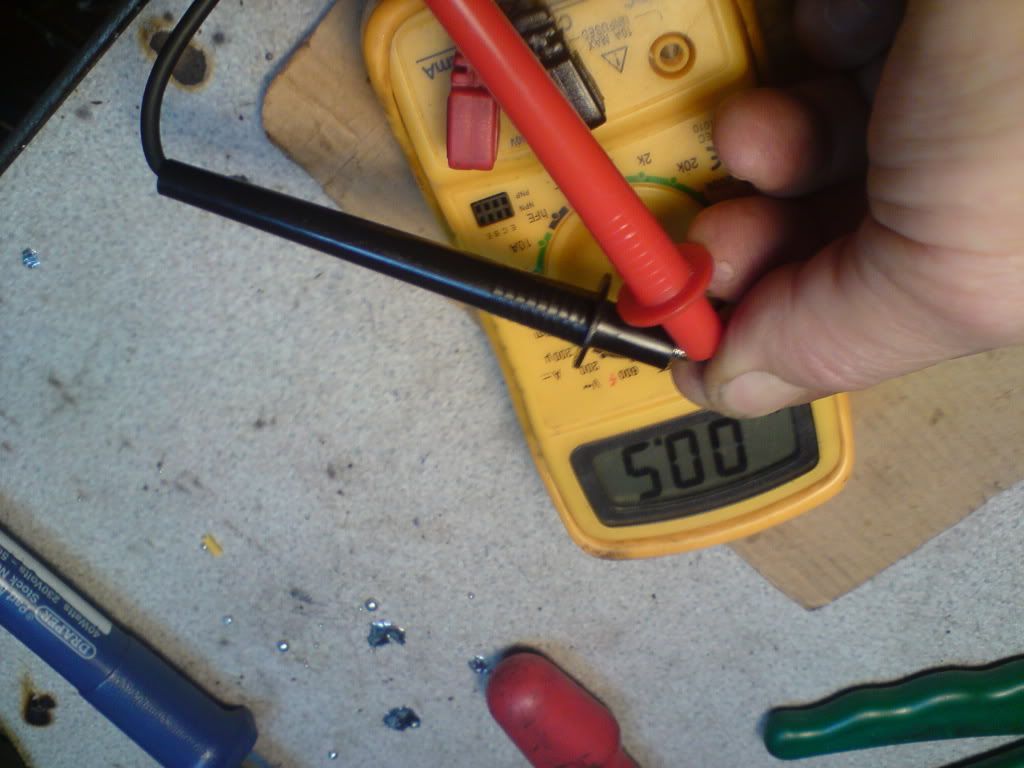
Then checking connections for same reading.....a higher reading would show a poor connection...
This conversion is for a lad In Ireland...He will be fitting a heat sink to the back of this rectifier, and that will hold the Zenor Diode.... Making it a one piece kit, needing only a battery to complete the conversion.... the stator was finished some weeks ago....