Discussion on Electronic Stators
Posted: Wed Feb 08, 2012 11:46 pm
Hi, I am in the process of having a go at rewinding my own stator and have become aware after a bit of research that there are design issues which I do not fully understand. So, I thought it would be an idea to start a thread where I can document my progress and hopefully attract the wealth of knowledge evident on this forum.
I am currently running a full DC conversion using a BGM stator as the basis but fitted with 2 SIL lighting coils following damage to the originals caused by one of the mag housing nuts coming undone. I then had a SIL stator rewound at West Country Windings which I fitted and was very happy with the improved output. Unfortunately the windings were destroyed within 150 miles on the way to the Euro in Ireland. West Country rewound it but TBH I was not happy with the way that it was done, not bobbins were used and I was reluctant to use it with the coils wound directly onto the powder coated laminates.
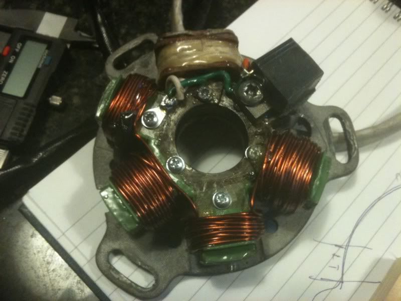
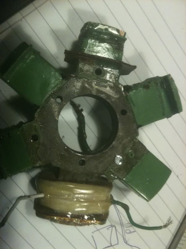
So, I have removed the windings in an attempt to understand how the additional output was achieved and I have been donated 2 duff SIL stators to use for experimentation. Here’s the West Country Stator before:
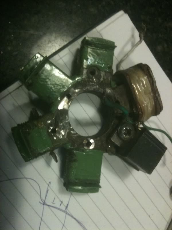
And with the windings removed
My observations so far are as follows:
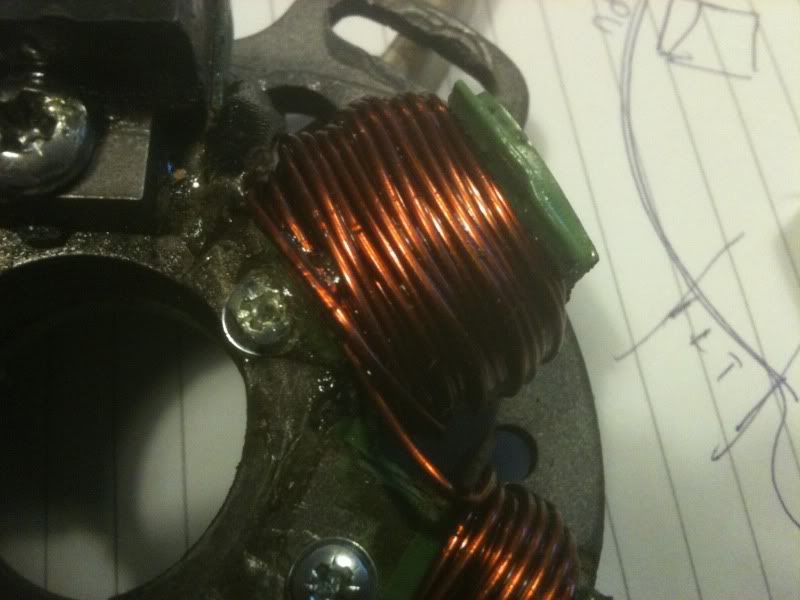
Coil wire gauge is 1.25mm (18 AWG) on both the West Country and the SIL
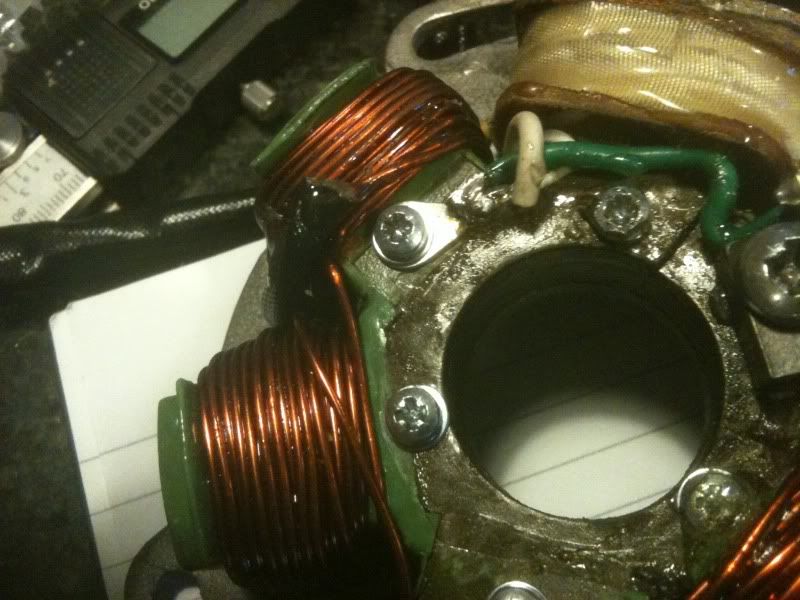
Coils are wound in alternating directions Clockwise (C/W) and Anti Clockwise (Anti C/W) on both stators. Counting from the Pickup in the direction of flywheel rotation, coil 1 anti C/W, coil 2 C/W, coil 3 anti C/W and coil 4 C/W. This has been explained on another thread:
My next move is to unwind the coils on one of the donated SIL coils (thanks to Toddy, Soulsurfer and Storkfoot) and rewind using at least the same number of turns as used on the West Country stator. The temptation though would be to add as many turns as possible without fouling the flywheel but is it possible to go too far? I know of Hysteresis losses in inductor cores (magnetic saturation/inertia) might that cause excess heat in the coils?
Anyway, enough conjecture for now, all thoughts/ theories and suggestions welcomed, my electrical theory is limited to a City & Guilds taken back in 1972, it wasn’t very clear then and is VERY cloudy now.
I am currently running a full DC conversion using a BGM stator as the basis but fitted with 2 SIL lighting coils following damage to the originals caused by one of the mag housing nuts coming undone. I then had a SIL stator rewound at West Country Windings which I fitted and was very happy with the improved output. Unfortunately the windings were destroyed within 150 miles on the way to the Euro in Ireland. West Country rewound it but TBH I was not happy with the way that it was done, not bobbins were used and I was reluctant to use it with the coils wound directly onto the powder coated laminates.
So, I have removed the windings in an attempt to understand how the additional output was achieved and I have been donated 2 duff SIL stators to use for experimentation. Here’s the West Country Stator before:
And with the windings removed
My observations so far are as follows:
Coil wire gauge is 1.25mm (18 AWG) on both the West Country and the SIL
Coils are wound in alternating directions Clockwise (C/W) and Anti Clockwise (Anti C/W) on both stators. Counting from the Pickup in the direction of flywheel rotation, coil 1 anti C/W, coil 2 C/W, coil 3 anti C/W and coil 4 C/W. This has been explained on another thread:
The next thing I noticed was that there are 2 different sizes of bobbin used, coils 2 and 4 are significantly smaller than coils 1 and 3 with correspondingly less turns on them. Im not sure why this is, it could be due to proximity to the adjacent coils but I’m not so sure.firekdp wrote:Coaster, the coils are alternately wound because, at any one time there will be an opposite pole affecting them. A north magnetic pole will will generate an opposite polarity to a south pole. If the adjacent coils were wound the same way it would be like connecting batteries with the positives together, ie no current would flow. As you're winding lighting coils it doesn't matter which direction you wind them, as long as they alternate.
My next move is to unwind the coils on one of the donated SIL coils (thanks to Toddy, Soulsurfer and Storkfoot) and rewind using at least the same number of turns as used on the West Country stator. The temptation though would be to add as many turns as possible without fouling the flywheel but is it possible to go too far? I know of Hysteresis losses in inductor cores (magnetic saturation/inertia) might that cause excess heat in the coils?
Anyway, enough conjecture for now, all thoughts/ theories and suggestions welcomed, my electrical theory is limited to a City & Guilds taken back in 1972, it wasn’t very clear then and is VERY cloudy now.