
So it assumes that the scooter is fitted with a typical stator, flywheel, CDI, regulator kit.
___________________________________________________________________________
Parts needed :
- Single phase rectifier [eg the Wassell units as mentioned in other threads]
12v battery [4.5 Ah is ample for “standard†lights]
Fuse & fuse holder
DC horn
terminals, cable, sleeving etc
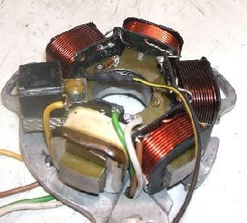
Remove the stator
Make a mark to enable it to be refitted in the same position, which should retain your existing ignition timing.
Modify the stator
Each end of the coils on the stator needs to be connected to the rectifier.
So the existing earth tag should be removed, and an additional wire added.
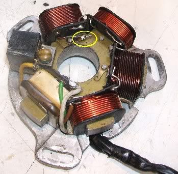
Unsolder the wire as indicated above, and solder a new wire to the end of the coil windings. Use heatshrink to insulate this from the stator plate.
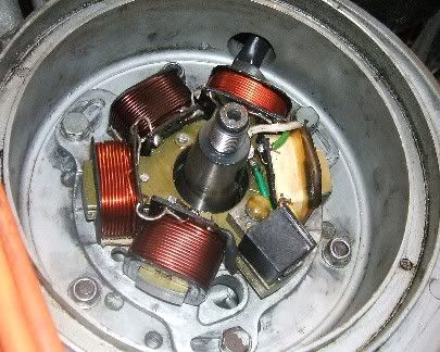
Feed this new wire though the plate to join the other wires. Sleeve the cables from the stator.
Refit the stator
Make sure the wires are not trapped or likely to snag on anything. The cables to the CDI can now be reconnected.
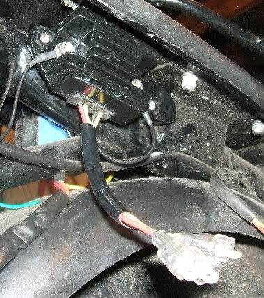
Fit the rectifier
Next, work out how long you need the leads from the rectifier to be, then cut, sleeve and add terminals.
Remove the old regulator unit, and fit the new rectifier [as the mounting spaces are different, new mounting holes may need to be made], earthing the black to one of the fixing points.
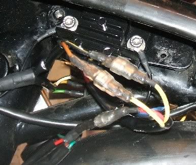
Connect the wires
Connect the wire from the stator that went to the regulator* to one of the yellow leads on the rectifier; and the new wire you just fitted on the stator to the other yellow. It doesn’t matter which way round these are.
*This wire was brown on the stator we were doing, but could be yellow [or something else...] on another stator; two stators can even have the same colour wire doing a different job ~ always check what the wire is actually connected to rather than relying on the colour of the insulation
The cable[s] that did go to the output side of the regulator is[are] connected to the red lead from the rectifier. The +ve side of the battery should also be connected here. Doing it this way will mean that in the event of the battery losing its charge the lights will still work when the engine is running.
Fit a fuse
A fuse should also be fitted either in this +ve lead to the battery, or on the –ve earth side of the battery. If it is fitted on the +ve side, do it after the feed into the loom, as again this will ensure that the lights still work if the fuse blows [although of course the cause of the fuse blowing should be traced and fixed as soon as you can].
Fit the battery
Make sure the battery is secure and that the +ve terminal cannot short out on anything.
Tidy the wire routing
Allow for any moving parts and securely neatly with cable ties.
Replace the horn
Worth inspecting the terminals here too and changing if necessary.
It may also be worthwhile checking your ignition timing with a strobe again.
___________________________________________________________________________
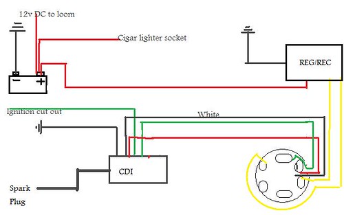
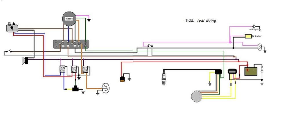
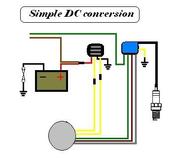
A simple diagram of the conversion :
___________________________________________________________________________
Use decent terminals, insulation and heatshrink throughout.
This conversion will not be sufficient to run extra lights etc for any length of time; if Pathfinders for example are to be used then ideally the stator should be rewound, or the standard lights could be run off the AC using a Vespa type 5-pin rectifier, but that’s beyond the scope of this article. Relays would also be needed if the current is increased to this extent.
___________________________________________________________________________
The scooter we did this conversion on today had an Indian stator, with BGM LED rear lamp, LED sidelights and standard bayonet fitting 35/35w halogen headlamp bulb. A 7.2Ah battery was fitted.
Without the engine running the draw with all lights on was 2.4A; the current on the battery became positive at around 2100 rpm. So this means at fairly low revs the battery is getting more than it is being required to supply. Therefore there should be no problems with the battery draining if all the lights are used.
We fitted a Readspeed bulb; this raised it to 2.8A and needed 2300rpm to get a positive current reading on the battery, but the light did seem much better. And again, perfectly adequate for keeping the battery charged whilst riding with all lights on.
Thanks to CraigH for the use of his bike for photos etc
This piece is meant to be written as a simple guide to converting a typical Lambretta to DC; please comment if it is unclear or I have missed out any steps.
Hopefully it will be useful for what should be fairly representative of many people’s needs.
Jarv