
Carving Windows in a Piston
-
sean brady scooters

- Dealer
- Posts: 2040
- Joined: Mon Jan 05, 2009 12:09 pm
- Location: Ripon, North Yorkshire
- Contact:
dave is correct.... 
Sean Brady Scooters - 01765 690 698

He's correct, you'll get the different inlet characteristics along with a restricted flow cos of the reed maybe at higher speeds? I'm not sure why you would go to the expense of the reed and not take full advantage of it.sean brady scooters wrote:dave is correct....
After all looking at the before and after of some of the conversions the gains are minimal anyway when completed in full so what can be expected from just doing this?
Is this a tune you would recommend Sean?
-
sean brady scooters
- Dealer
- Posts: 2040
- Joined: Mon Jan 05, 2009 12:09 pm
- Location: Ripon, North Yorkshire
- Contact:
I totally agree with you Adam
I think its a REAL shame to not go for the boost ports/either single ,double or triple...
to make the most from this set up....after making it reed valve with 360 intake..
I think its a REAL shame to not go for the boost ports/either single ,double or triple...
to make the most from this set up....after making it reed valve with 360 intake..
Sean Brady Scooters - 01765 690 698
I never really understood the terminology given to this - 360deginlet.
Realistically it can't be ever 360 deg can it.
Maybe it should have been called something more like 'variable inlet and blow back reduction system' kinda trips off the Tongue hey.
Realistically it can't be ever 360 deg can it.
Maybe it should have been called something more like 'variable inlet and blow back reduction system'
Ai, the piston holes give a longer inlet duration which brings me back to my original query - what's the best vertical position for the piston hole(s)? No doubt there are plenty of schools of thought on this but is there a basic principle?
I have read the following way of doing it:
Assemble the top end on the engine. Move the piston to BDC. Scribe the shape of the inlet port on the piston through the port. Disassemble the top end and remove material from the scribed area.
That's all cool and makes sense BUT if the holes were lower then at least part of the holes would be open to the inlet port for longer whilst the piston is battering up n down. But would this be beneficial? Does that make sense?
I know where you are all coming from regarding boost ports but I thought I'd give it a go without for a start, and the piston holes are something I can achieve in my garage with my limited kit. I hope for better torque and the 'variable inlet and blow back reduction system' should defo give better mpg, something that this tight wad will appreciate. And if it does run poo I'll hold my hands up.
Looking at the position of the ring pegs on the Asso piston one central boost port won't be feasible so it'll need two little uns I reckon.
I have read the following way of doing it:
Assemble the top end on the engine. Move the piston to BDC. Scribe the shape of the inlet port on the piston through the port. Disassemble the top end and remove material from the scribed area.
That's all cool and makes sense BUT if the holes were lower then at least part of the holes would be open to the inlet port for longer whilst the piston is battering up n down. But would this be beneficial? Does that make sense?
I know where you are all coming from regarding boost ports but I thought I'd give it a go without for a start, and the piston holes are something I can achieve in my garage with my limited kit. I hope for better torque and the 'variable inlet and blow back reduction system'
Looking at the position of the ring pegs on the Asso piston one central boost port won't be feasible so it'll need two little uns I reckon.
I wouldn't go for BDC. Think how you want them to work with a boost port and when you want them to be open and this will give you your answer.
I'm not sure how you would be able to do this but comparing say the position of the piston holes relative to the inlet port on say a standard GT kit, TS1 and RB would be a good start. Maybe someone on here has some port maps.
This would show you if the EXACT location plus boost port timing affects engine characteristics and more importantly why.
This would show you if the EXACT location plus boost port timing affects engine characteristics and more importantly why.
Good shout. I've got the dimensions of the windows of a standard TS1 piston so if anyone has the following I should be able to do something similar to my piston:soullad wrote:I'm not sure how you would be able to do this but comparing say the position of the piston holes relative to the inlet port on say a standard GT kit, TS1 and RB would be a good start. Maybe someone on here has some port maps.
This would show you if the EXACT location plus boost port timing affects engine characteristics and more importantly why.
1) The height and width of the exhaust port of a std TS1 barrel and,
2) The distance from the top of the exhaust port to the gasket face at the top of the barrel.
Cheers.
A pic of the piston through the inlet port at BDC and TDC would be ace too................
COME ON SEAN YOU'VE JUST DONE ONE!! 
IMO your going down the wrong route here......and over complicating it.
Your future boost port will be usually open in line with your transfers. Mock the top end up and rotate the crank till the trans are just opening. This is where you want charge to flow through the windows of the piston and start to exit through the boost port. Draw a line on your piston from inside the inlet port. Now you have a reference point.
Now all thats to decide is do you want the windows to start to open in line with the boost port, if so have the hole 'bottom' on the line. Or fully open when the boost starts to open have the hole 'top' on the line. Or anywhere in between.
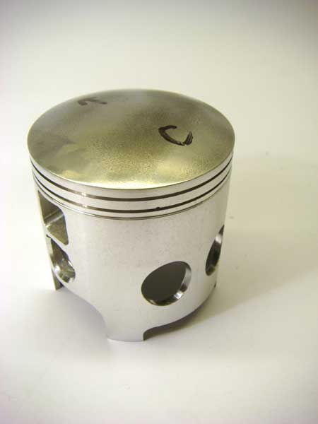
Boost ports don't tend to flow that much anyway so massive windows are questionable. Why not just cut two round ones, they will be stronger, flow sufficient amounts of gas etc....Like the MB pistons......
What about your inlet port are you modding that at all, apart from the boost port?
Hope that makes sense.
Adam
IMO your going down the wrong route here......and over complicating it.
Your future boost port will be usually open in line with your transfers. Mock the top end up and rotate the crank till the trans are just opening. This is where you want charge to flow through the windows of the piston and start to exit through the boost port. Draw a line on your piston from inside the inlet port. Now you have a reference point.
Now all thats to decide is do you want the windows to start to open in line with the boost port, if so have the hole 'bottom' on the line. Or fully open when the boost starts to open have the hole 'top' on the line. Or anywhere in between.
Boost ports don't tend to flow that much anyway so massive windows are questionable. Why not just cut two round ones, they will be stronger, flow sufficient amounts of gas etc....Like the MB pistons......
What about your inlet port are you modding that at all, apart from the boost port?
Hope that makes sense.
Adam
Yes, that all makes sense thanks.
And round holes certainly would be easier to do.....just drill them out and then smooth them with some emery or wet & dry.
Not going to be doing anything to the inlet, other than match the manifold, and won't be putting in a boost port to start with. Just gunna run it with the holey piston and see how it goes. But the holes need to be in the right spot for when (or if) I add a boost port. Cheers.