Sneak Peak
fantastic work.
win or lose have a booze
A few more .
 20210804_123217 by mark christie, on Flickr
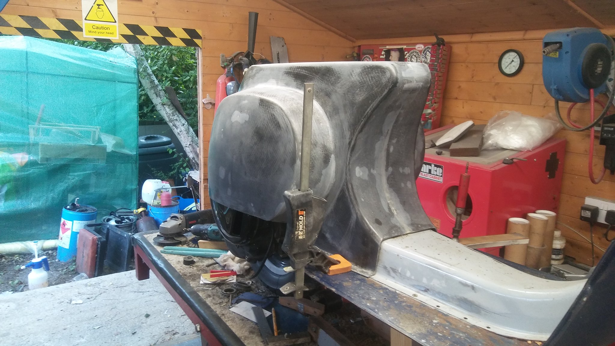
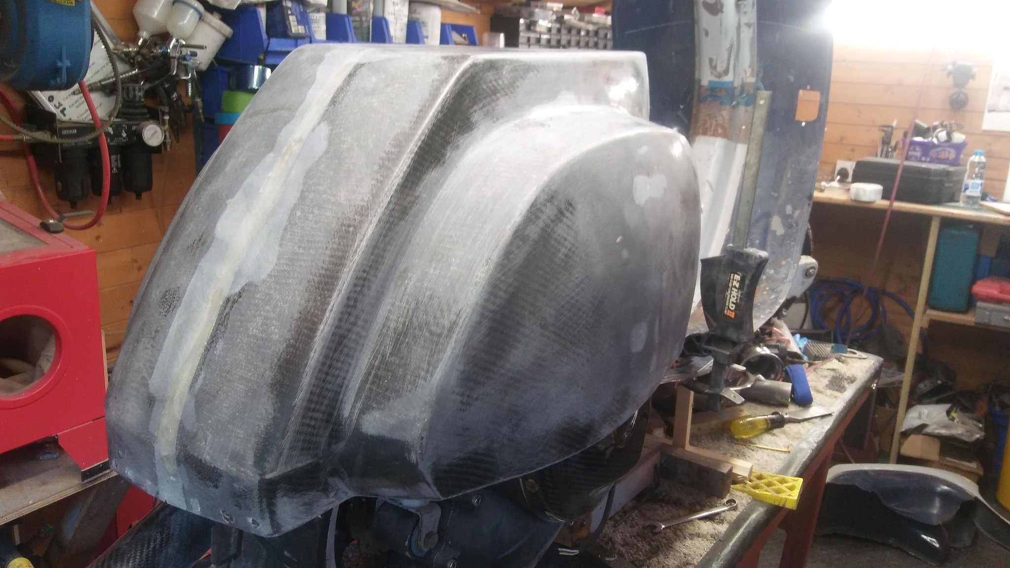
This one shows the cut and re shut rear end parts just sat in place to get a few dimensions for the frame.
 20210804_123517 by mark christie, on Flickr
 20210804_123526 by mark christie, on Flickr
 20210804_123217 by mark christie, on Flickr
This one shows the cut and re shut rear end parts just sat in place to get a few dimensions for the frame.
 20210804_123517 by mark christie, on Flickr
 20210804_123526 by mark christie, on Flickr
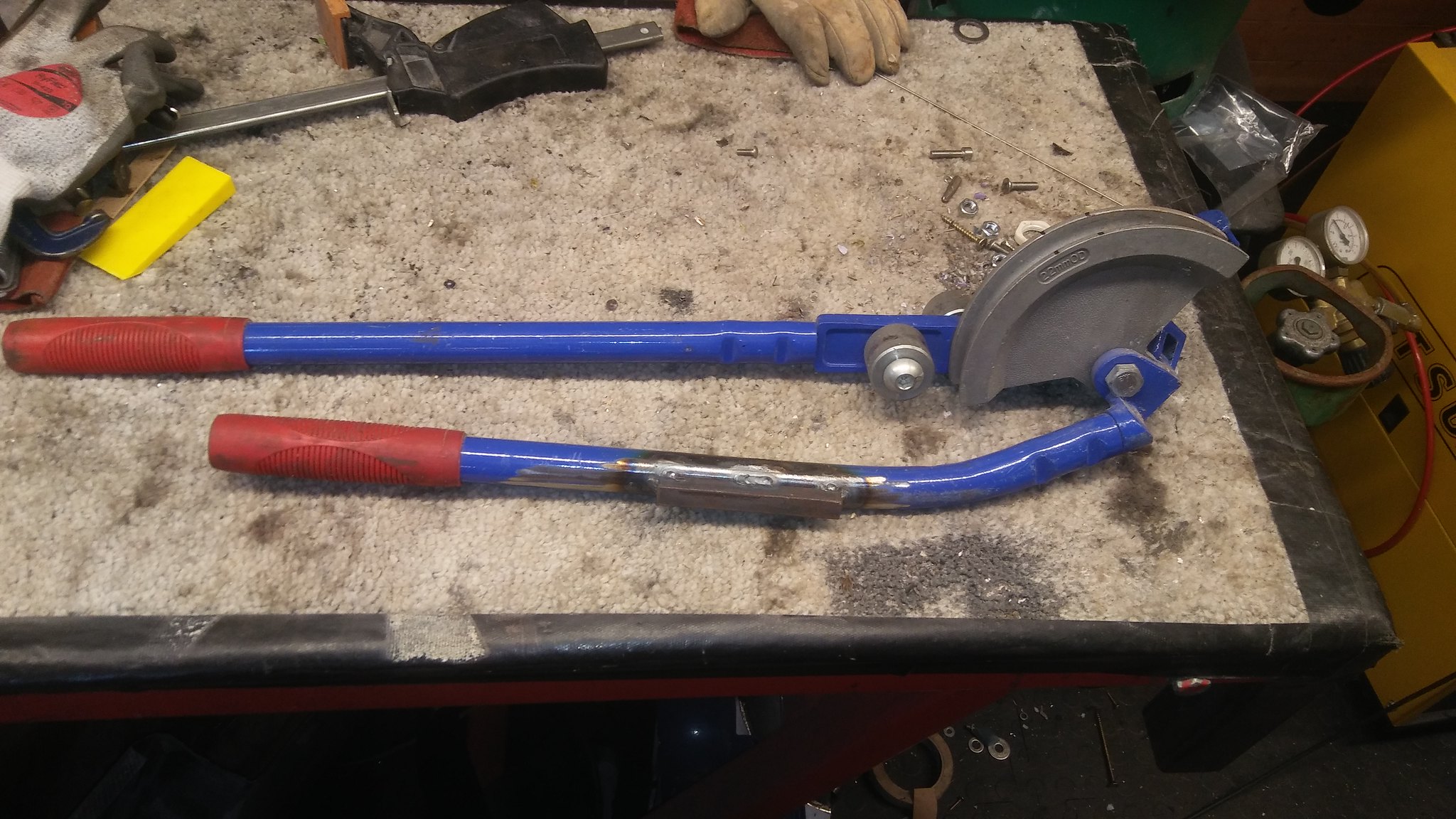
On with the show, framework next. The framework to support the rear end section is made from 20mm steel tube. We use a lot of this at work and is nice to bend and tig weld. I have a cheap plumbers pipe bender that I've welded some flat bar to so that it clamps nice in the vice. Most of the tube to tube welds I cut using a 20mm hole saw. This gives a good close fit for welding.
 20210918_142350 by mark christie, on Flickr
 20210822_090536 by mark christie, on Flickr
 20210822_090545 by mark christie, on Flickr
Its been a while since I did any tig welding to any degree. I've had a tig welder at home for about 10 years and changed it to an AC/DC tig welder a couple of years ago to tackle any aluminium jobs that needed doing. The company I work for has gone through a lot of changes over the years and we are onto our fourth owner. Our workshop is now very small and has no welding bays and the machine shop has gone. So no more home jobs at work.
 20210918_142350 by mark christie, on Flickr
 20210822_090536 by mark christie, on Flickr
 20210822_090545 by mark christie, on Flickr
Its been a while since I did any tig welding to any degree. I've had a tig welder at home for about 10 years and changed it to an AC/DC tig welder a couple of years ago to tackle any aluminium jobs that needed doing. The company I work for has gone through a lot of changes over the years and we are onto our fourth owner. Our workshop is now very small and has no welding bays and the machine shop has gone. So no more home jobs at work.
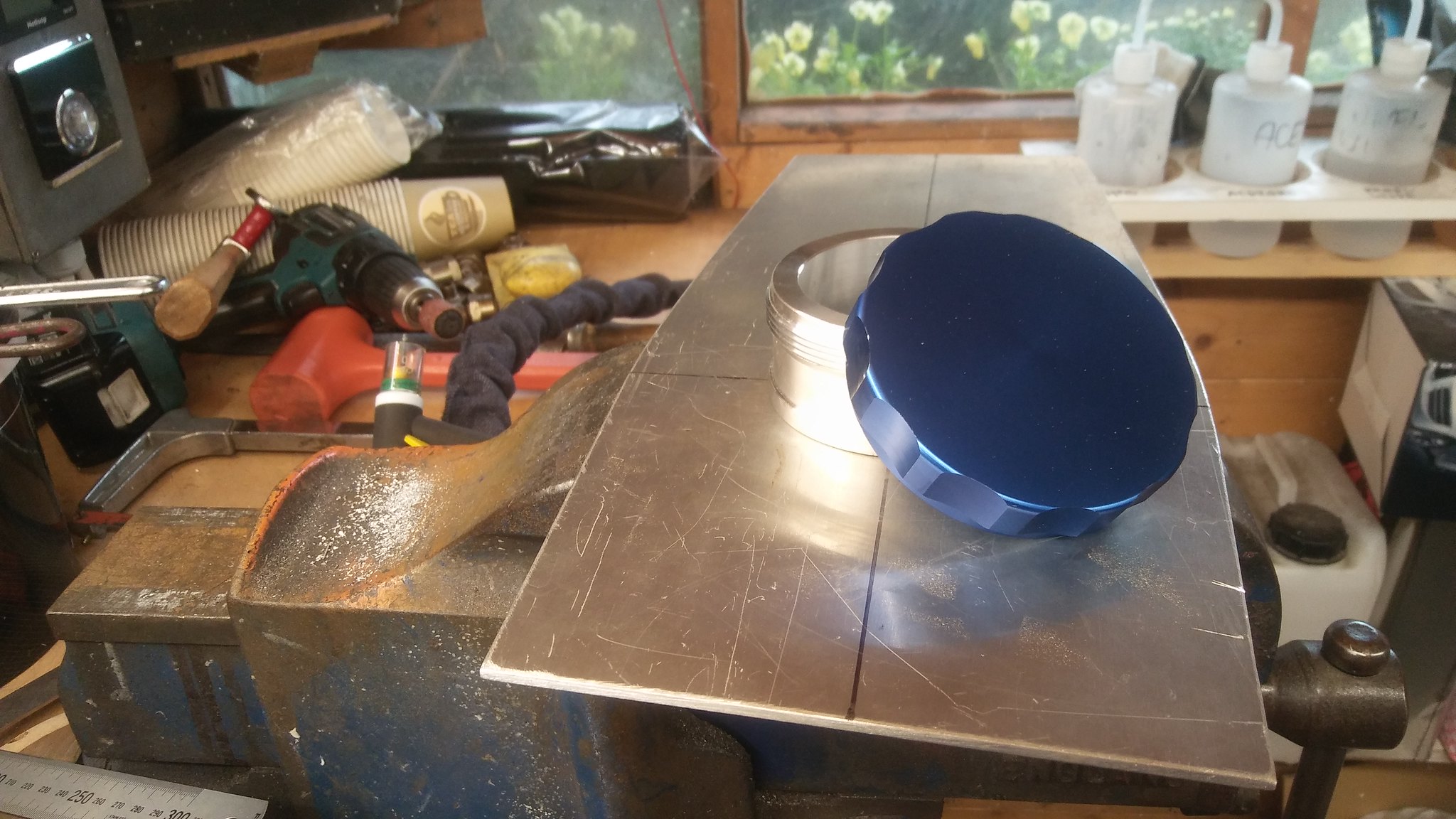
A few more, the fuel tank is next. Due to the tube framework I was unable to use the standard Vespa PK tank. I mocked up a tank in the space available using card, paper and masking tape. Next was to transfer the patterns to a flat sheet of 3mm aluminium. Ally tig welding the tank was fun to do, I haven't done it for ages so spent a little time with some test pieces.
 20210822_090545 by mark christie, on Flickr
 20210903_135216 by mark christie, on Flickr
 20210903_151124 by mark christie, on Flickr
The filler cap/neck was bought from Amazon and was only £7, the tap is a fast flow BGM.
 20210903_151020 by mark christie, on Flickr
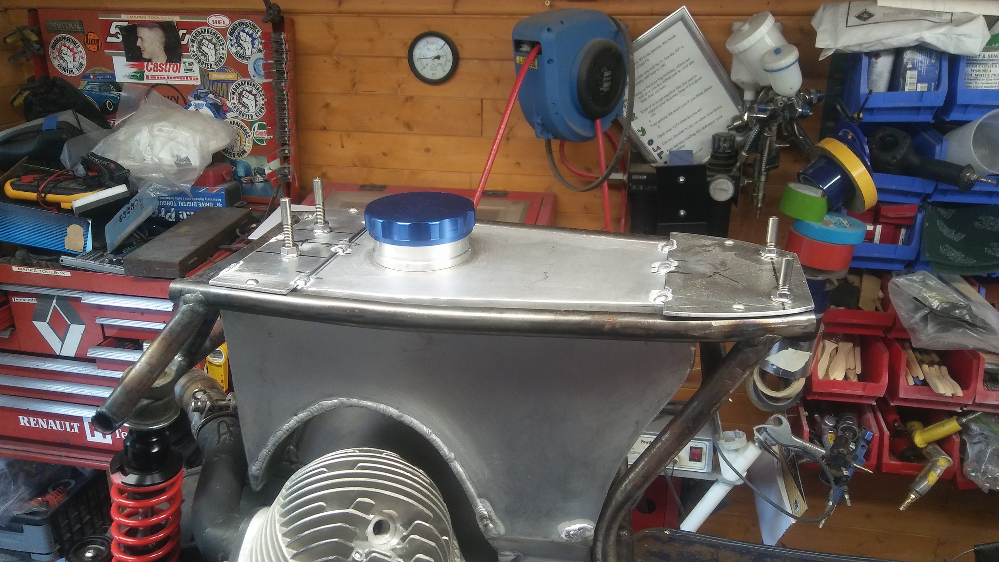
Tank fitted to the frame with tabs welded on to hold the seat and to secure the tank to the frame.
 20210908_153349 by mark christie, on Flickr
 20210822_090545 by mark christie, on Flickr
 20210903_135216 by mark christie, on Flickr
 20210903_151124 by mark christie, on Flickr
The filler cap/neck was bought from Amazon and was only £7, the tap is a fast flow BGM.
 20210903_151020 by mark christie, on Flickr
Tank fitted to the frame with tabs welded on to hold the seat and to secure the tank to the frame.
 20210908_153349 by mark christie, on Flickr
At this point I thought is was a good idea to fit a fuel sender in case I want to fit a fuel gauge. This will also give access for a 32mm socket to the fuel tap nut. Fuel sender bought also from Amazon about £20, it has a float that rises up a stainless steel shaft that has a coil of wire in it. 0 to 190 ohms, that suits most fuel gauges.
 20210918_104709 by mark christie, on Flickr
 20210918_121504 by mark christie, on Flickr
 20210908_153438 by mark christie, on Flickr
I'll try and get a bit more done at the weekend. I'm off to Singapore for work at the end of the month for 4 to 6 weeks. So progress will be halted for a while.
 20210918_104709 by mark christie, on Flickr
 20210918_121504 by mark christie, on Flickr
 20210908_153438 by mark christie, on Flickr
I'll try and get a bit more done at the weekend. I'm off to Singapore for work at the end of the month for 4 to 6 weeks. So progress will be halted for a while.
A little more done, I made some ally plates to mount the battery tray, fuel pump and electrics on. I will be changing the regulator/rectifier for a full wave unit. I think the one supplied is only a half wave unit and I need to run quite a lot of DC items from the battery. The ally plates may get changed to carbon fibre closer to completion.
 20210912_130811 by mark christie, on Flickr
 20210912_130803 by mark christie, on Flickr
The leg shields have now been fully removed and all the spot weld holes welded.
 20210912_130811 by mark christie, on Flickr
 20210912_130803 by mark christie, on Flickr
The leg shields have now been fully removed and all the spot weld holes welded.
Good afternoon gents, so I have a few more pictures and a little update. It's been a little slow in the shed, the company I work for are back into full swing and are busy. This entails a fair bit of world wide travel. To speed up making moulds I bought a set of fibreglass PK leg shields from a Italian dealer along with a load of over items. The leg shields are utter shite, and if they hadn't take an absolute age to arrive I would have sent the junk back. As you can see from the pictures they are made from a PK frame that must of had a few dents and problems. They are have been made to a very poor standard and are full of filler, putty and spray filler. They were then poorly spray painted. The paint I took off with acetone on a rag then spent days digging out the filler and making good.
 20211229_115005 by mark christie, on Flickr
 20211229_115021 by mark christie, on Flickr
 20211229_115330 by mark christie, on Flickr
 20211229_115342 by mark christie, on Flickr
 20211229_115005 by mark christie, on Flickr
 20211229_115021 by mark christie, on Flickr
 20211229_115330 by mark christie, on Flickr
 20211229_115342 by mark christie, on Flickr
Next I grafted on a belly pan/spoiler. this was bolted on then filled in and blended. The hole part was then sprayed with polyester primer then with a couple of heavy coats of polyester high gloss mould top coat. This is then sanded with various grades of wet and dry then machine polished to a high gloss shine. This we call a " plug" in the trade, next stage is to turn the plug into a mould by grafting on wide flanges to allow for resin infusing the carbon fibre.
 20211229_125031 by mark christie, on Flickr
 20211229_125044 by mark christie, on Flickr
 IMG_20220323_114945 by mark christie, on Flickr
 IMG_20220325_141307 by mark christie, on Flickr
 IMG_20220325_141316 by mark christie, on Flickr
 20211229_125031 by mark christie, on Flickr
 20211229_125044 by mark christie, on Flickr
 IMG_20220323_114945 by mark christie, on Flickr
 IMG_20220325_141307 by mark christie, on Flickr
 IMG_20220325_141316 by mark christie, on Flickr