
top lad as allwaysRich_T wrote:I have all of these cranks and rods drawn on CAD, if you send me an Email I can help you out with the crank design. At the very least I can give you a drawing of the modified crank and what weights need to be put in and where. I can send you some screen shots of the schematics too.
Rotax 300 builld
Its in bits scooter club: www.facebook.com/groups/132415046859320
Agreed! Rich is a wealth of knowledge.
Ric, you mentioned moving the LC inlet to the base? Why's that? The head is half the original (motor was a twin) so the water jackets flow through the head and cylinder just like stock. With a water pump moving everything and a pressurized system, it shouldn't matter where the inlet is located. At least that's what I'm thinking, but I could be wrong.
The crank is indeed becoming a bit of a sore point, but I half expected this so it's no big surprise. Rich has educated me a bit on what he's doing with the wider web crank and CR250 rod and that sounds like it may well be the way to go. I've had a few estimates come through and they're all sky-high. One of the reasons I decided to do what I'm doing was the fact that the RB25 kits are $1000 and used Rotax barrels are under a hundred all day long on eBay. I figured I could blow up, port, and otherwise abuse these things until I was blue in the face and still be into it for pennies on the dollar. A $1000 crank upsets this idea quite a bit.
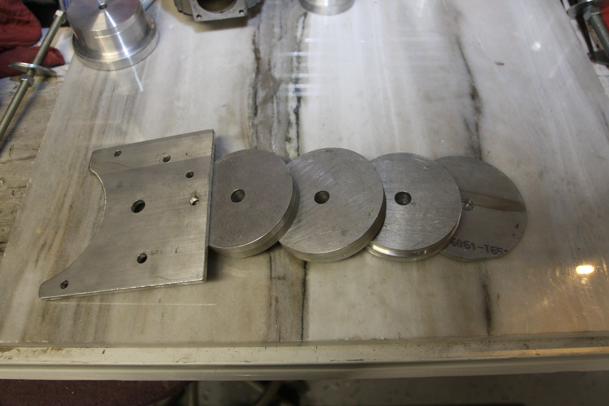
That said, i will probably shift gears and go with a shorter stroke crank to keep the cost down and adjust the barrel configuration as required. The adapter plate is 25mm and needs to be machined anyways to get the port timings in line. I was going to assemble the rotating assembly and then machine the plate back as required. I assume a shorter stroke crank will need that little bit more taken off the plate.
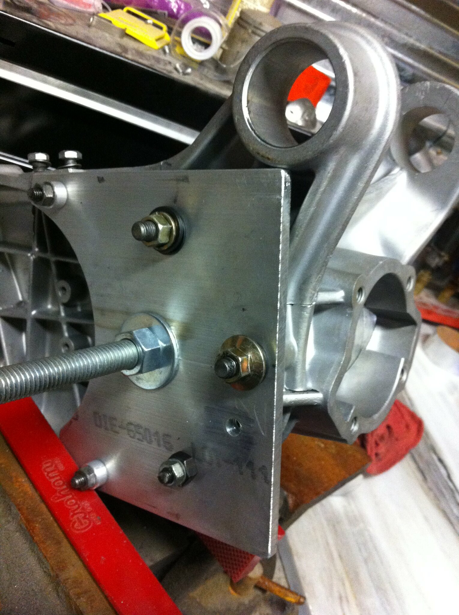
As for the cases distorting while being welded, I'm with you on that. Made a fixture to hopefully keep this down to a minimum. Need to make another to keep the mounts from moving as well. Preheating and a slow welding pace will also help I hope! Gonna TIG the small stuff and where it's necessary to build up some material, I've got a spool gun for the MIG machine to really pile on the filler.
 Rotax Lamby build-013 by PotvinV8, on Flickr
 Rotax Lamby build-012 by PotvinV8, on Flickr
 Rotax Lamby build-015 by PotvinV8, on Flickr
 Rotax Lamby build-014 by PotvinV8, on Flickr
Adam, I need to check the clearance between the barrel and the frame but I was thinking of doing exactly as you mentioned if it is a problem. Great minds and all that...
-Ryan
Ric, you mentioned moving the LC inlet to the base? Why's that? The head is half the original (motor was a twin) so the water jackets flow through the head and cylinder just like stock. With a water pump moving everything and a pressurized system, it shouldn't matter where the inlet is located. At least that's what I'm thinking, but I could be wrong.
The crank is indeed becoming a bit of a sore point, but I half expected this so it's no big surprise. Rich has educated me a bit on what he's doing with the wider web crank and CR250 rod and that sounds like it may well be the way to go. I've had a few estimates come through and they're all sky-high. One of the reasons I decided to do what I'm doing was the fact that the RB25 kits are $1000 and used Rotax barrels are under a hundred all day long on eBay. I figured I could blow up, port, and otherwise abuse these things until I was blue in the face and still be into it for pennies on the dollar. A $1000 crank upsets this idea quite a bit.
That said, i will probably shift gears and go with a shorter stroke crank to keep the cost down and adjust the barrel configuration as required. The adapter plate is 25mm and needs to be machined anyways to get the port timings in line. I was going to assemble the rotating assembly and then machine the plate back as required. I assume a shorter stroke crank will need that little bit more taken off the plate.
As for the cases distorting while being welded, I'm with you on that. Made a fixture to hopefully keep this down to a minimum. Need to make another to keep the mounts from moving as well. Preheating and a slow welding pace will also help I hope! Gonna TIG the small stuff and where it's necessary to build up some material, I've got a spool gun for the MIG machine to really pile on the filler.
Rotax Lamby build-013 by PotvinV8, on FlickrRotax Lamby build-012 by PotvinV8, on FlickrRotax Lamby build-015 by PotvinV8, on FlickrRotax Lamby build-014 by PotvinV8, on FlickrAdam, I need to check the clearance between the barrel and the frame but I was thinking of doing exactly as you mentioned if it is a problem. Great minds and all that...
-Ryan
Last edited by RManson on Wed Aug 30, 2017 9:12 pm, edited 1 time in total.
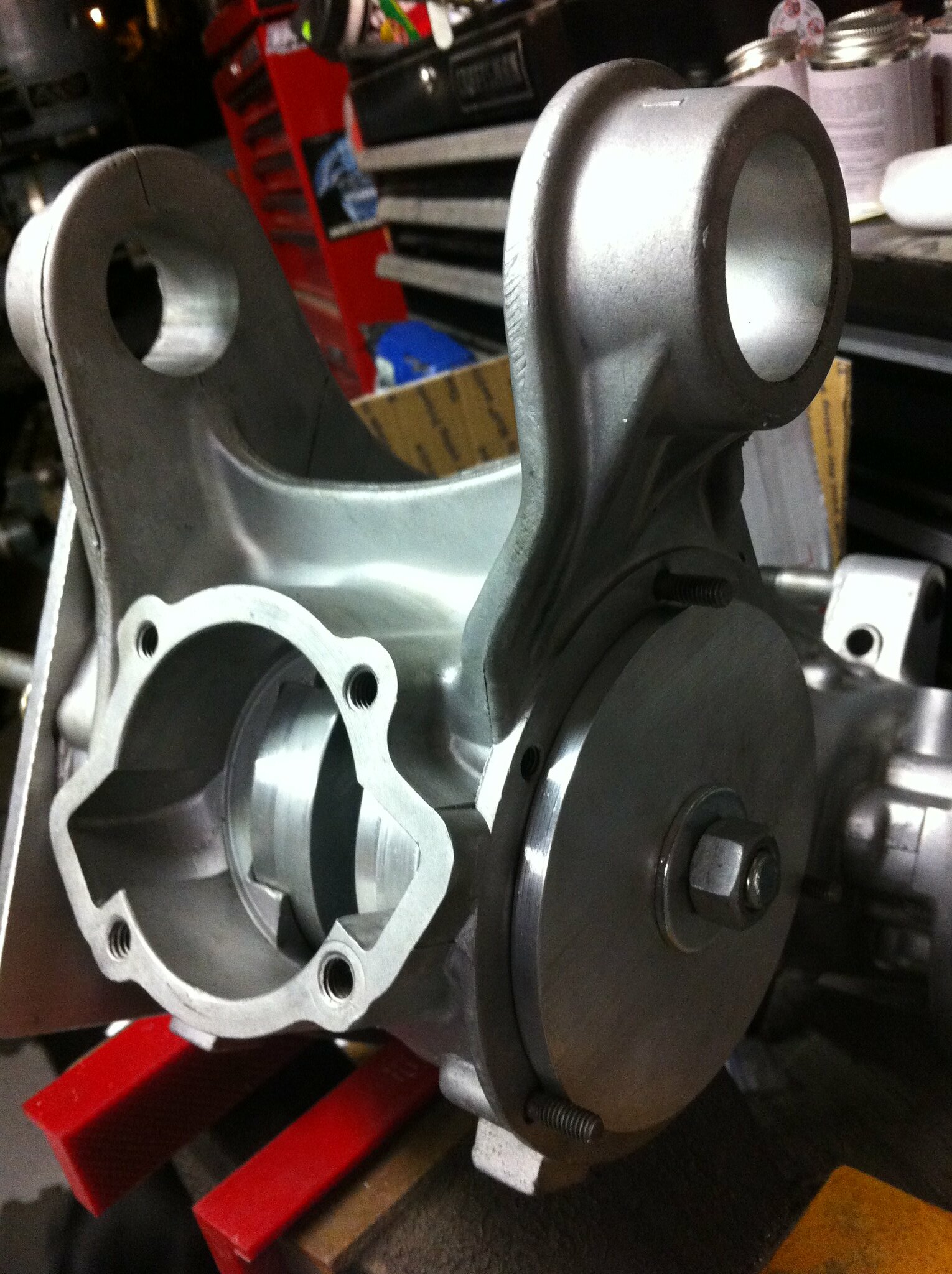
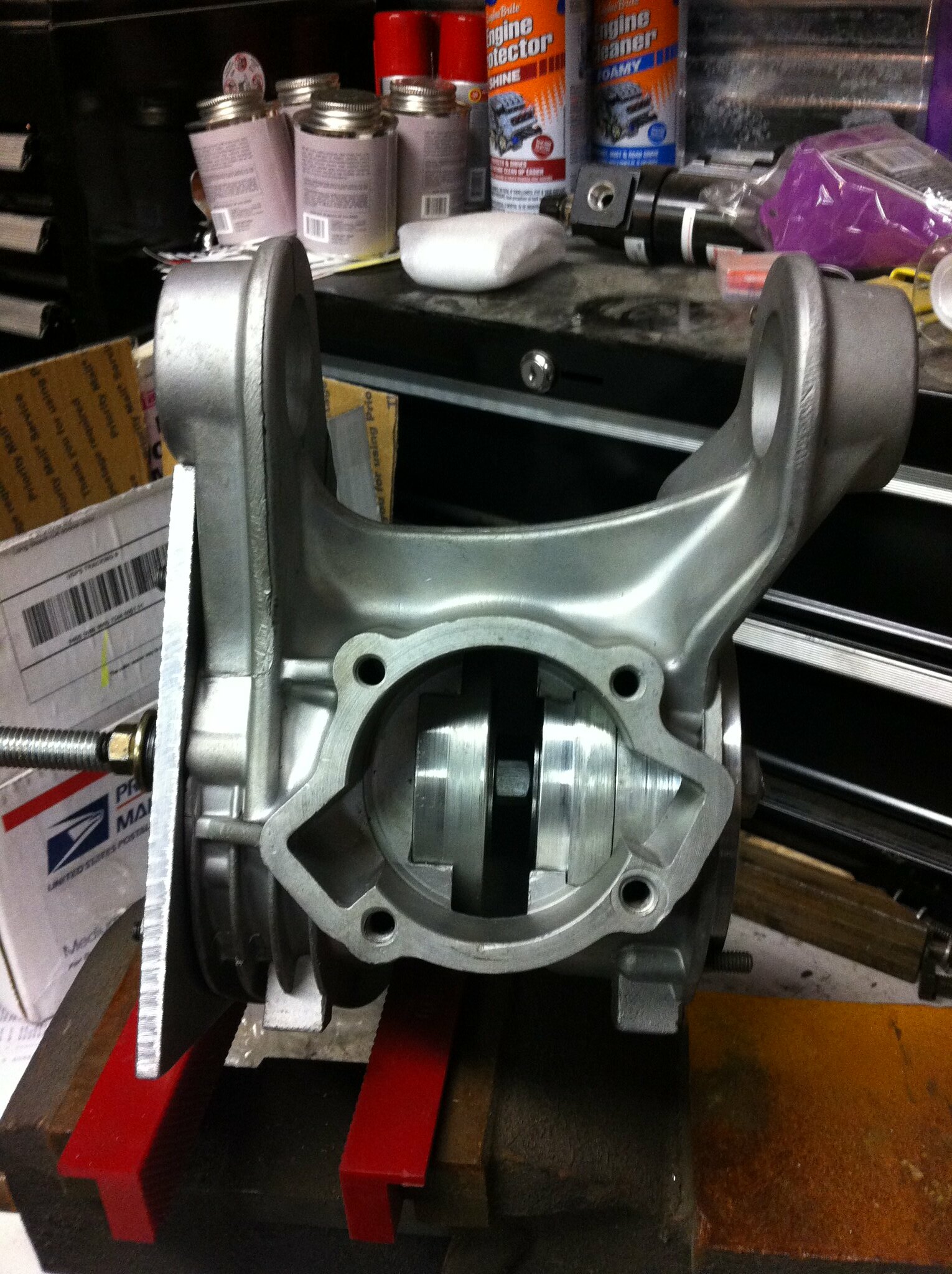
just that looking at the pic of top end there appears to be only the out let on the head for the pipe to the rads .. i was there fore assuming given the base gasket area that the pump on the case from which the barrel came off fed through the bottom of barrel ..i may be wrongRManson wrote: Ric, you mentioned moving the LC inlet to the base? Why's that?
Its in bits scooter club: www.facebook.com/groups/132415046859320
im assuming that the opening between the bottom two studs is for coolantRManson wrote:
as you say not really a biggie
Its in bits scooter club: www.facebook.com/groups/132415046859320
-
Adam_Winstone
- registered user
- Posts: 1693
- Joined: Tue Jan 31, 2012 8:54 pm
- Main scooter: Lambretta GP
- Contact:
I like the supports that you have to limit distortion. Whilst those shown should limit twisting, the twisting will show itself by the mount alignment going out of line, which then results in the whole motor being off line with the centre line of the scoot. I didn't pick up on the twisting to my casing until the mount started to allow the back wheel to get close to the rear mudguard under suspension travel! Thankfully, the motor/bike still handles as standard but it does highlight the care that needs to be taken when welding/machining casings.
Adam
Adam
 Rotax Lamby build-016 by PotvinV8, on Flickr
Hey Ric,
Actually both the inlet and the outlet are located in the head. On the stock engine, the pump must be located externally somewhere. You are correct about the water port on the bottom of the barrel, it goes into the crankcase only a short distance, i guess to cool the crank slightly? On my engine, all it would cool is the bottom of the new case plate, so blocking it isn't an issue. The coolant will enter the head, pass through the barrel, then exit the head, so it's all self contained.
Adam,
I agree and I think I will fab up a set of jigs similar to those in the crankcase to tie the mount together, then attach them to the mag flange to essentially tie that area together. From there, I think something to keep the mag flange and rear brake backing plate in line would be a good idea as well. Unfortunately, things tend to move when welded, but with a bit of planning, these distortions can be greatly minimized.
As soon as the crank is sorted, I'll start knocking it together in earnest. Anybody have any thoughts on where to locate the reed valve inlet on the top of the crankcase? Should I tie the top port into the inlet or do you think the crankcase pressure will suffer? Is there rule of thumb as to where to best locate the inlet in terms of relation to the crank or shall I just pick a good area and knock a hole into the crankcase to drop in the reed valve manifold?
Thanks guys!
-Ryan
Last edited by RManson on Wed Aug 30, 2017 9:15 pm, edited 1 time in total.
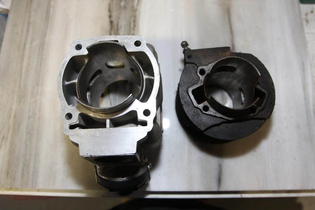
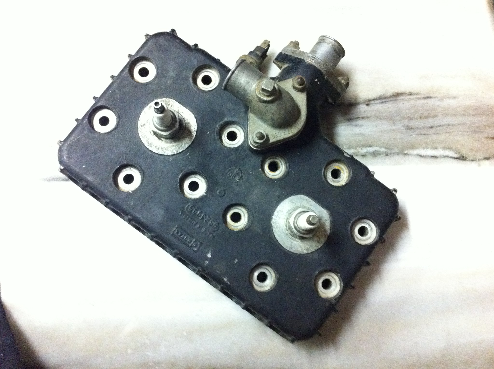
Correction! Finally found some parts illustrations that shed a bit of light on the water passages as well as receiving some advice from Rich_T regarding coolant flow. It seems Ricspeed is correct in that the Rotax motor pumps coolant up from the crankcase through the base of the barrel, around the exhaust port, and up through the heads. The two ports on top of the head threw me off at first until Rich_T mentioned the need to cool the exhaust off first. Upon further inspection, what Ric said about there being a lower inlet is completely correct. You learn something everyday and I imagine there will be many more 'a-ha' moments to come!
RManson wrote: One of the reasons I decided to do what I'm doing was the fact that the RB25 kits are $1000
Ughumph...Where are they $1000 Guatamala, Aleutian Islands ?
-
Muttley McLadd

- registered user
- Posts: 1496
- Joined: Wed Jan 07, 2009 6:32 pm
- Contact:
Here, they're $900 plus postage. Plus taxes when it lands. That's well over $1000.Yanker wrote: Ughumph...Where are they $1000 Guatamala, Aleutian Islands ?
CakeAndArseParty
Here in the states by the time you add a head, tax, and shipping it's getting darn close to that. But the price of the kit isn't the topic of this thread, I was simply stating one of the reasons I decided to do what I'm doing.Yanker wrote:RManson wrote: One of the reasons I decided to do what I'm doing was the fact that the RB25 kits are $1000
Ughumph...Where are they $1000 Guatamala, Aleutian Islands ?